

How Much Current Should A S5 K12g Amp Draw
- #23
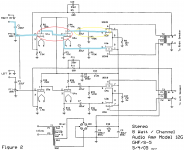
One thing I notice nearly your schematic: Information technology shows Pentode Mode output stages. But you said y'all are using the 1609 transformers in Ultra Linear Mode. It is one or the other (unless you go Triode Wired).
For Ultra Linear and Triode Wired modes, I propose using 4 each 100 Ohm resistors (one to each screen connection).
You lot should have fun listening when you wire one up for the second time.
Last edited:
- #25
Some pentodes may oscillate in either Ultra Linear mode or in Triode Wired fashion.
The 100 Ohm resistors would exist connected directly correct on the socket screen connections.
UL: The other finish of the 100 Ohm resistors would go to the right Ultra Linear taps (plate and screen of the same 1/2 of the secondary).
Triode Wired: The other end of the 100 Ohm resistors would go to the plate connexion of the same tube.
This is an easy one to try if yous similar experimenting.
The Edcor XPWR025-120 should work OK for your amp.
And I am surprised, information technology has an 11.6V filament winding.
For anybody who uses a 12.6V transformer filament secondary, only uses four 10GV8 xi.6V tubes:
Save your tubes from pre-mature failure
The 10GV8 filament is eleven.6V @ 0.45A
Most transformers have 12.6V output, not eleven.6V output.
You need 11.6V @ 1.8A (0.45A ten 4 = 1.8 A).
12.6V - 11.6V = 1V Drop 0.5V per leg.
0.5V / 1.8A = 0.28 Ohms
(1.8A squared) 10 0.28 Ohms = 0.ix Watts heating, use either two iii Watt or ii 5 Watt 0.28 Ohm resistors.
Last edited:
- #26
Thank you for explaining that. I'll try your suggestions one time I go to that point. Sound pretty straightforward.
I know for sure that my transformer is 11.6 on the heater winding at 2A, so I recall I'm good there. I call up this may be why I picked this transformer originally because it had the spec'd tube heater voltage available. My business organisation was with the 180V winding at 200 mA capacity. I had read that the original was closer to 300 mA. PRR mentioned that it'd probably be fine only I'm but trying to exist certain. I didn't want to motion forward with the wiring just to find out that the transformer can't supply the necessary amperage.
John
Last edited:
- #28
Ok guys, I'm going to take your discussion for it. I really appreciate your help so far.
I take attached a paint modified schematic.
Tin can someone explicate why the cherry circled line does not take a coupling capacitor? I would remember that the B+ would be feeding into the grid on tube 2A. I would retrieve it would need to be similar to the yellow circumvolve.
I understand that V2A and V4A are beingness used a stage splitters. Too that V2B, V1B, V4B, and V3B are amplifying. I only think I know this from watching Uncle Doug and Blueglow Electronics on youtube. What I don't know is the function of V1A and V3A.
What I'm getting at is where should I use shielded wire? I'm trying to determine the audio path but I likewise want to empathise where high voltage might be and prevent the use of sheided wire. I have highlighted in bluish what I think it the audio path...for 1 channel.
Thank you,
John
-
S5-Electronics-K12G-Tube-Amp-Kit-Schematic~2.png
119.8 KB · Views: 175
Last edited:
- #xxx
JTCamp,
Exist careful of shielding.
With a very low impedance signal source driving the input, and then when the 100k pot wiper is turned to 50k (worst case condition), the pot wiper output impedance is 25k. This impedance has to drive the capacitance of the shield wire, the filigree to cathode capacitance, and the 1+ Miller capacitance of the input tube. This might decrease the loftier frequency response. This outcome could be even worse if the signal source is a high impedance, depending on where the pot wiper is prepare.
Similar effects are true for the other stages; where plate impedance in parallel with plate load 150k or 47k (and cathode impedance in parallel with 47k) have to drive the shield wire capacitance and grid capacitances.
Short shielded wires that are low capacitance per pes will probably not exist a trouble; but that requires attention to the distance and shielded wire specifications.
Y'all have a series of three areas where the shield wires might have an effect. Suppose the capacitance of each of those 3 areas are -one dB at 40 kHz. That would be a total of approximately -three dB at 40kHz, and -ane dB at 20kHz.
I do non use shielded wires on my amplifiers, and I am able to get the output ripple to be less than 500uV, with several amps with less than 100uV. That requires good layout; wiring placement; transformer, asphyxiate and OPT orientation and spacing; and good attending to footing loops . . . particularly the loop of the first and 2nd cap of the B+; equally well every bit the ground loops of both the input and output connectors. I do not use negative feedback (which sometimes amp designers utilize when attempting to reduce hum).
Last edited:

Source: https://www.diyaudio.com/community/threads/k12g-questions.328989/page-2
Posted by: jonesuner1965.blogspot.com
0 Response to "How Much Current Should A S5 K12g Amp Draw"
Post a Comment